Featured Workshops


Filter Videos
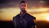
Grooming Techniques using XGen, Unreal & Marmoset Toolbag with Guillermo Cortes

Guillermo Cortés
2h 24m 54s
9 Lessons
Adding Nuts, Bolts & Cables to Sci-Fi Models with Bryant Momo Koshu

Bryant Momo Koshu
28m 53s
3 Lessons
Advanced Real-Time FX Workflows for AAA Games with Fabio M. Silva

Fabio M. Silva
3h 57m 32s
11 Lessons
Frame-by-Frame Workflow using ZBrush, Maya & UltraClay with Alexander Lee

Alexander Lee
5h 25m 58s
12 Lessons
Blender, Cycles, Photoshop & After Effects Workflow with Chris Beatty

Chris Beatty
1h 11m 6s
3 Lessons
Maya Workflow for Blocking, Animating & Polishing with Gang Trinh

Gang Trinh
2h 17m 41s
6 Lessons
Character Animation Techniques using Maya & Unreal with Taylor Whitsett

Taylor Whitsett
5h 15m 44s
14 Lessons
Real-Time Cinematic Workflow using Unreal, Blender & Houdini with Kosuke Iwasaki

Kosuke Iwasaki
32m 17s
8 Lessons
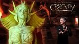
Concept, Design & Rendering Techniques in Photoshop with Steve Firchow

Steve Firchow
3h 31m 18s
8 Lessons
Texturing, Lighting, Animation & Rendering Techniques With Eric Keller

Eric Keller
4h 44m 17s
20 Lessons
Beginner’s Guide to Modeling & Animation Workflows with Eric Keller
Eric Keller
5h 26m 9s
25 Lessons
Beginner’s Guide to Getting Started in Maya with Eric Keller
Eric Keller
4h 10m 6s
20 Lessons
Simulating Fluid Interactions with David Silberbauer

David Silberbauer
4h 37m 53s
8 Lessons
Mastering Character Performance in Maya with Alissar Kobeissi

Alissar Kobeissi
4h 11m 32s
8 Lessons
Production-Ready Workflow using Golaem, Maya & Unreal Engine with Wilfried Lhomme

Wilfried Lhomme
5h 2m 49s
14 Lessons
Production-Level Character FX Workflow with Saravmit Singh

Saravmit Singh
4h 56m 54s
10 Lessons
Concept to Final Comp using Photoshop, Nuke & Blender with Liane Xuelian Li

Liane Xuelian Li
2h 46m 3s
10 Lessons
Maya, ZBrush, Wrap & Photoshop Workflow with Adam Spring

Adam Spring
6h 46m 52s
17 Lessons
Hard-Surface Design, Modeling & Rendering Techniques with Kris Turvey

Kris Turvey
2h 59m 49s
9 Lessons
Shading Complex Curved Objects with Neville Page

Neville Page
2h 29m 44s
9 Lessons
Shading Cylinders, Cones & Spheres with Neville Page
Neville Page
2h 48m 28s
8 Lessons
Shading Planar Surfaces with Neville Page
Neville Page
2h 3m 15s
8 Lessons
Step-by-Step VFX Workflow using Houdini & Natron with Maria Barbadillo

Maria Barbadillo
3h 23m 22s
10 Lessons
Houdini, ZBrush & Unreal Engine Workflow with Giovani Magana

Giovani Magana
4h 18m 22s
13 Lessons
Mari, ZBrush, Nuke & Houdini Workflow with Sohrab Esfehani

Sohrab Esfehani
6h 33m 1s
23 Lessons

Designing Actions for Games & Cinematics with Brad Faucheux

Brad Faucheux
4h 47m 59s
12 Lessons
Photoshop, Maya, Materialize & Arnold Workflow with Tony Ianiro

Tony Ianiro
4h 23m 38s
11 Lessons
Photoshop, Maya & Arnold Workflow with Tony Ianiro
Tony Ianiro
5h 12m 48s
14 Lessons
Creating a Sinkhole Sand Effect with David Silberbauer
David Silberbauer
6h 18m 29s
9 Lessons
Houdini & Nuke Workflow for Lighters & Generalists with Andreas Kjær-Jensen

Andreas Kjaer-Jensen
6h 7m 43s
16 Lessons
Light & Composite a Shot using Maya & Nuke with Graham Cunningham

Graham Cunningham
4h 27s
17 Lessons
Modeling, Texturing & Rendering Techniques with Joshua Haun

Joshua Haun
6h 6m 16s
17 Lessons
Houdini, Maya & Nuke Workflow with Josh Harrison

Josh Harrison
5h 1m 27s
12 Lessons
ZBrush, Maya, Marvelous Designer & Substance Painter Workflow with Antonio Mossucca

Antonio Mossucca
8h 31m 27s
18 Lessons
Substance 3D Modeler, ZBrush & Blender Workflow with Corey Gooch

Corey Gooch
7h 30m 24s
15 Lessons
Maya & Marmoset Toolbag Workflow with Madhav Shyam

Madhav Shyam
10h 24m 35s
17 Lessons
Animating Game Creatures Using Maya with Christian Brierley

Christian Brierley
7h 28m 44s
14 Lessons
Intermediate Environment Workflow using World Creator & Blender with Koke Nunez

Koke Nunez
3h 23m 54s
8 Lessons
Lighting & Rendering using KeyShot & Photoshop with Neville Page
Neville Page
3h 54m 13s
17 Lessons
Designing Characters in ZBrush with Neville Page
Neville Page
3h 36m 30s
16 Lessons
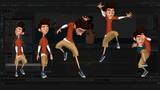
Advanced Animation Techniques with Stephen Cunnane

Stephen Cunnane
5h 1m
7 Lessons
Mari, Maya & Gaffer Workflow with Michal Zsigmund

Michal Zsigmund
4h 11m 47s
8 Lessons
Professional Houdini Workflow with Salah Hussein

Salah Hussein
4h 25m 1s
10 Lessons
Houdini & Nuke Production Workflow with Jon Perez

Jon Perez
4h 29m 38s
14 Lessons
Making a Fully Textured, Game-Ready Character with Omid Moradi

Omid Moradi
7h 53m 23s
20 Lessons
From Concept to Final Sculpt using ZBrush, Maya & Marvelous Designer with Omid Moradi
Omid Moradi
4h 48m 12s
12 Lessons
Character Animation & Interactive Gameplay Workflow with Bill Buckley

Bill Buckley
3h 3m 40s
8 Lessons
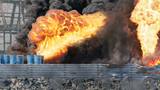
Creating a Desert Car Scene with Alvaro J. Segura

Alvaro J. Segura
3h 17m 28s
16 Lessons
Story Development & Creative Workflow with Tiago Sousa

Tiago Sousa
2h 6m 46s
9 Lessons